How to Choose the Right Anchor Bolt for Your Project?
Choosing the right Anchor Bolt begins with the load, not the product catalog. A bolt holding a steel column faces different demands from one securing a handrail or equipment base. Tension, shear, fatigue, vibration, corrosion, edge distance, and concrete strength all influence the selection. A familiar diameter may still fail when installation conditions change.
Industry guidance provides a reliable starting point. The American Institute of Steel Construction’s Steel Construction Manual and Design Guide 1 explain anchorage design principles for steel connections. ASCE/SEI 7-22 establishes design loads for wind, seismic activity, and other environmental forces. ASTM F1554 classifies anchor rods by strength and application, including Grades 36, 55, and 105. The International Building Code also connects anchor design with concrete, structural, and fire-safety requirements. These references should be checked together, not treated as isolated rules.
Details matter.
Experienced contractors inspect hole diameter, embedment depth, thread condition, washer size, and tightening access before installation. Manufacturer test data can also reveal differences between adhesive, expansion, cast-in, and screw-type anchors. Yet a specification sheet never replaces sound judgment. A high-strength Anchor Bolt may be unsuitable for weak concrete, damaged edges, or severe corrosion exposure. Even published guidance has limits, especially when site conditions differ from laboratory testing. The safest decision combines engineering calculations, verified product data, competent inspection, and the actual conditions found on site. Mistakes often begin with an assumption that appears reasonable.
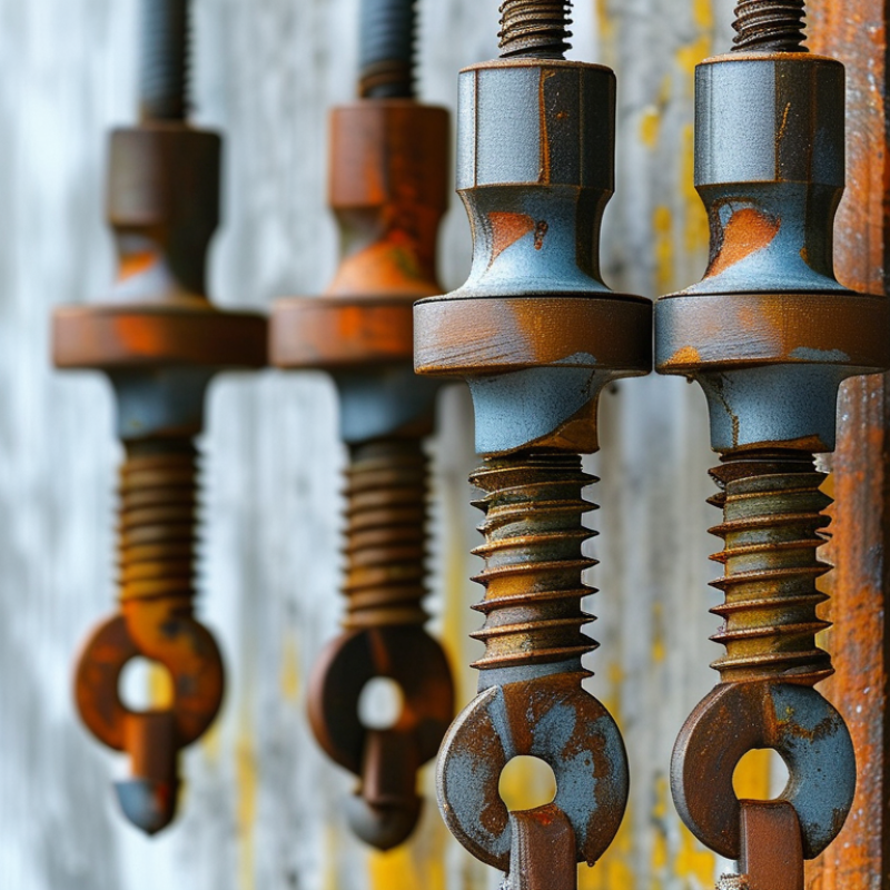
Classify Anchor Types by Load, Base Material, and ACI 318-19 Design Scope
Choosing the right anchor bolt begins with the load, not the bolt diameter. Separate tension, shear, and combined loading. A ceiling-mounted frame may pull outward, while a guardrail can create prying forces near the edge. Cast-in anchors suit new concrete and offer predictable embedment. Post-installed mechanical anchors work well for many retrofit conditions. Adhesive anchors can provide deep engagement, but temperature, hole cleaning, and curing time matter greatly.
Then classify the base material. Normal-weight concrete, lightweight concrete, masonry, and hollow block do not behave alike. A fastener approved for cracked concrete may not be suitable for masonry. ACI 318-19 Chapter 17 provides design requirements for anchors installed in structural concrete. Check cracked or uncracked conditions, concrete strength, edge distance, spacing, embedment, and seismic demand. The code scope does not automatically cover every substrate or installation method. That distinction is easy to miss.
Tips: Record the actual concrete strength and thickness before selecting an anchor. Inspect drilling dust, hole depth, and installation torque on site. Follow the tested installation procedure. Do not treat a stronger bolt as a stronger connection. I have seen oversized anchors fail because edge distance was ignored. A quick chart helps, but it can mislead. When loads combine or consequences are serious, have a qualified engineer verify the design and field conditions.
Calculate Tension, Shear, and Seismic Demand Using ASCE 7 Load Combinations
How to Choose the Right Anchor Bolt for Your Project?
Calculate Tension, Shear, and Seismic Demand Using ASCE 7 Load Combinations
Anchor bolt selection should begin with design forces, not bolt diameter. Under ASCE 7 load combinations, calculate factored tension and shear from dead, live, wind, and seismic actions. Include uplift, overturning, eccentricity, and load transfer through the base plate. The critical combination may be 0.9D plus wind, or a seismic combination containing vertical and horizontal earthquake effects. Use the project’s adopted ASCE 7 edition. Small wording differences matter.
For seismic design, compare the anchor group demand with concrete breakout, pullout, steel strength, pryout, and edge-distance limits. ACI 318 Chapter 17 provides the anchor-strength framework, including cracked concrete conditions. The 2023 USGS National Seismic Hazard Model reports that nearly 75% of the United States could experience damaging earthquake shaking, affecting about 230 million people. That figure makes seismic checks practical, not theoretical. A spreadsheet can look precise and still be wrong. I recheck load directions and base-plate stiffness because those details are often missed.
Tips: Keep tension and shear units consistent. Check the weakest anchor first. Record embedment depth, spacing, edge distance, and concrete strength. Review installation tolerances before approval. Do not assume a larger bolt solves every failure mode; shallow embedment or thin concrete may control. When demands interact, use the applicable tension-shear interaction equation rather than checking each force separately.
Reference: ASCE 7-22, ACI 318-19, and the USGS 2023 National Seismic Hazard Model.
Select Diameter and Embedment with ACI 318-19 Concrete Failure Checks
Choosing an anchor bolt starts with the load path, not the catalog diameter. Identify tension, shear, load combinations, cracked concrete, edge distances, and spacing. In field reviews, I often find that a large bolt cannot solve poor detailing. A 20 mm bolt may fail because the concrete edge breaks first.
ACI 318-19 Chapter 17 requires separate checks for steel strength and concrete failure. For tension, check concrete breakout, pullout, and side-face blowout where applicable. For shear, check concrete breakout, pryout, and steel strength. Calculate the effective embedment depth rather than relying on the drilled hole depth. Reinforcement, member thickness, and nearby anchors can reduce the available breakout area. Use the correct strength-reduction factors and apply load interaction when tension and shear act together.
A practical selection begins with the smallest diameter that passes every required limit state. Then increase embedment only when it improves the governing concrete resistance. More depth is not always useful. For example, a bolt near a 100 mm edge may still fail in breakout, even with substantially deeper embedment. I prefer to sketch the failure surfaces before finalizing the layout. It exposes mistakes early. I still recheck assumptions against the actual concrete condition, installation tolerance, and anchor type. A qualified structural engineer should verify the final design, especially for cracked concrete, seismic loading, or thin members. Typical errors include treating nominal strength as design strength and ignoring nearby reinforcement. Their consequences are not obvious on site.
How to Choose the Right Anchor Bolt for Your Project? — Select Diameter and Embedment with ACI 318-19 Concrete Failure Checks
The following preliminary selection matrix compares common anchor diameters and effective embedments using an illustrative cast-in anchor calculation. Final anchor design must also verify edge distance, spacing, concrete breakout, pullout, side-face blowout, shear breakout, steel shear, tension–shear interaction, seismic requirements, installation tolerances, and the project-specific load combinations.
Anchor Diameter
(in.) | Nominal Diameter
(mm) | Effective Embedment, hef
(in.) | UNC Tensile Stress Area
(in²) | Steel Tension, φNsa
(kips) | Concrete Breakout, φNcb
(kips) | Governing Preliminary Check | Preliminary Design Comment |
| 1/2 | 12.7 | 4 | 0.1419 | 4.60 | 6.84 | Steel tension | Suitable for light-to-moderate tension loads when edge distance and spacing are adequate. |
| 5/8 | 15.9 | 5 | 0.2260 | 7.32 | 9.55 | Steel tension | Provides increased steel area while maintaining a moderate embedment depth. |
| 3/4 | 19.1 | 6 | 0.3340 | 10.82 | 12.55 | Steel tension | A balanced option for higher tension demands in sound, adequately reinforced concrete. |
| 7/8 | 22.2 | 7 | 0.4620 | 14.99 | 15.83 | Steel tension | Increasing embedment helps concrete capacity approach the available steel capacity. |
| 1 | 25.4 | 8 | 0.6060 | 19.64 | 19.30 | Concrete breakout | Further diameter increases may not improve capacity unless embedment and concrete geometry also increase. |
| 1-1/4 | 31.8 | 10 | 0.9690 | 31.39 | 27.06 | Concrete breakout | A larger bolt requires a concrete-focused design, including spacing, edge distance, and reinforcement effects. |
Calculation Basis and Design Assumptions
| Design reference | ACI 318-19 Chapter 17 anchoring-to-concrete provisions; values shown are preliminary screening values, not a stamped design. |
| Concrete strength | Normal-weight concrete with f′c = 3,000 psi; λa = 1.0. |
| Anchor type used for comparison | Cast-in headed anchor with a nominal steel yield strength of 36 ksi for the steel tension comparison. |
| Concrete breakout model | Isolated anchor in tension, no nearby edge, no group reduction, no eccentricity, and ψ-factors equal to 1.0. The calculation uses Nb = 24λa√f′chef1.5. |
| Strength reduction factors | φ = 0.90 for the steel tension comparison and φ = 0.65 for the concrete breakout comparison, subject to the applicable ACI 318-19 conditions. |
| Thread data | UNC tensile stress areas are standard nominal values for the listed diameters and are used only to compare threaded steel tension capacity. |
| Required additional checks | Verify factored tension and shear demand, edge distance, anchor spacing, fixture geometry, concrete thickness, pullout, pryout, shear breakout, steel shear, combined loading, cracking condition, corrosion exposure, and installation requirements. |
Selection principle: Increase diameter when steel strength, nut bearing, washer dimensions, or shear demand controls. Increase effective embedment when concrete breakout controls, provided that the slab or foundation thickness, reinforcement layout, edge distance, and required development length can accommodate the deeper anchor.
Match Steel Grade and Corrosion Protection to Exposure and Service Life
How to Choose the Right Anchor Bolt for Your Project?
Choosing an anchor bolt starts with more than load capacity. Steel grade must suit the design force, temperature, and installation method. However, exposure often controls long-term performance. Indoor, dry spaces may need standard carbon steel. Outdoor areas require stronger corrosion protection. Coastal air, deicing salts, and chemical fumes demand closer evaluation.
Galvanized bolts can provide practical protection in many damp environments. For constant moisture, chloride exposure, or aggressive chemicals, stainless steel may offer a safer service-life choice. Match the coating to the environment, not only to the product price. Check bolt strength, nut compatibility, coating thickness, and concrete conditions together. Field inspections often reveal a simple problem: damaged threads after installation. That small defect can become a serious corrosion path. A specification may look correct but still be poorly matched to actual exposure.
Tips: Confirm the exposure category before selecting steel. Review drawings, site drainage, and nearby chemicals. Keep dissimilar metals separated when galvanic corrosion is possible. Protect cut or damaged surfaces according to the approved repair method. Do not rely on appearance alone. It can mislead. Recheck the expected service life with a qualified engineer, especially where replacement access is limited. Some projects need a conservative choice; others only need better detailing. That judgment deserves honest review.
How to Choose the Right Anchor Bolt for Your Project?
Match the bolt steel grade to the required tensile strength, then select corrosion protection according to exposure conditions and the intended service life.
Dry indoor exposure Plain carbon-steel bolts may be suitable when moisture and corrosive chemicals are controlled.
Outdoor or humid exposure Use a zinc coating system, such as electroplating or hot-dip galvanizing, after checking coating thickness and installation requirements.
Marine or chloride exposure Consider corrosion-resistant stainless steel or a qualified heavy-duty protection system. Check chloride resistance, galling risk, and galvanic compatibility.
Minimum nominal tensile-strength values shown are based on ISO 898-1 property classes: 4.6 = 400 MPa, 8.8 = 800 MPa, 10.9 = 1,040 MPa, and 12.9 = 1,220 MPa. Actual anchor-bolt selection must also consider shear, edge distance, embedment, fatigue, temperature, installation torque, and the design code applicable to the project.